Lab 10 1
Summary:
In this lab we investigated multilayer switching and learned how to use simulation mode to inspect packets.
I had no issues completing the lab
Summary of understanding:
- How do you set the IP and subnet mask on different interfaces of a multilayer switch?
- From the configure terminal mode you can go into an interface and set it using the ip address command like the following:
ip address 192.168.1.1 255.255.255.0
- How do you enter simulation mode in Packet Tracer?
- You click the bottom right button that says simulation mode
- How do you set which types of packets you want to see in Simulation Mode?
- You click the edit filters button in the simulation mode menu.
Simple Routing Lab
Objective: Configure and observe a simple routed network.
Goals:
- Observe the Layer 2 header changes as a packet crosses a router
- Recognize the role of the default gateway
Part 1 - Configuring the Network
-
Start by downloading and opening the Packet Tracer file for this lab: lab10-1-starter.pktDownload lab10-1-starter.pkt
-
The network should look something like this:
- Assign the following IP information to the PCs:
- PC0:
- IP: 192.168.1.10
- Default Gateway: 192.168.1.1
- PC1:
- IP: 192.168.2.20
- Default Gateway: 192.168.2.1
- PC2:
- IP: 192.168.3.30
- Default Gateway: 192.168.3.1
- All subnet masks will be /24
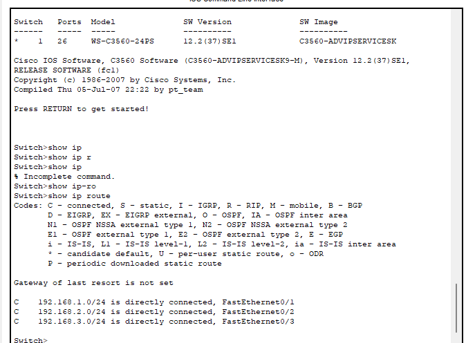
- Now, we'll need to set the interface that each PC is connected to on the multilayer switch to match the gateway IP we just defined, since this switch also has layer 3 routing capabilities and will serve as the gateway for all three machines. Click on the multilayer switch and enter the following IPs on these interfaces:
- FastEthernet0/1: 192.168.1.1
- FastEthernet0/2: 192.168.2.1
- FastEthernet0/3: 192.168.3.1
- All subnet masks will be /24
Note that because each port is a distinct interface, they all have to be given their own address.
- Once all of the interfaces are configured, try pinging PC1 and PC2 from PC0. If configured correctly, the pings should succeed!
- Note that sometimes the first ping request between two machines will time out - this is just a relic of Packet Tracer, and subsequent pings should succeed.
Q1: SUBMIT screenshots of a successful ping between PC0 and PC1 (2 points) and a successful ping between PC0 and PC2 (2 points)

- Click on the Simulation button in the bottom-right corner of the Packet Tracer window.
- A Simulation panel will appear on the right side of the window. Since Packet Tracer will simulate many protocols by default, click the 'Show All/None' button at the bottom of this window, and then click the 'Edit Filters' button. Check the ICMP box in the IPv4 tab of the window that pops up.
Now, ping PC1 from PC0. The initial ping packet should appear in the simulation window. Click the '►|' button a few times until the packet reaches PC1 - you should see the following packets in the simulation window:
If you click on the packet at the Multilayer Switch, you'll receive a summary of the OSI information the packet contains as it both arrives at and leaves the switch. In particular, at layer 2 you'll see something like 'AAAA.AAAA.AAAA >> BBBB.BBBB.BBBB' - this indicates that the packet is being sent from the MAC address AAAA.AAAA.AAAA to the MAC address BBBB.BBBB.BBBB. If you click on the Inbound and Outbound detail tabs, you can see how this information is specifically formatted within each packet.
Practice Saving Router config
- Save running config to NVRAM on Multilayer Switcher
- Check router to make sure Interface IP's are still there
- Submit Screenshot of Multilayer Switch showing IP address on an Interface/successfully run IOS command (1 Point)
Q2: SUBMIT answers to the following questions:
- What is the Source and Destination MAC address of the packet as it arrives at the switch? (1 point) SCREEN CAPTURE
- What is the Source and Destination MAC address of the packet as it leaves the switch? (1 point) SCREEN CAPTURE
- Why does the Destination MAC of the packet arriving at the switch nearly match the Source MAC of the packet leaving the switch? (3 points)
- This is because the packet is now being sent from the switch to pc1 as opposed to from pc0.

